Making a photogate
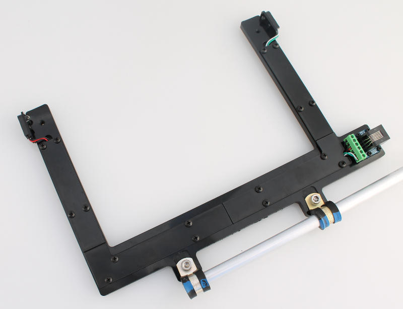
The photogate kit includes two pre-assembled photogates. The photogate assembly steps below are only included for informational purposes and for users intending to make their own DIY photogates.
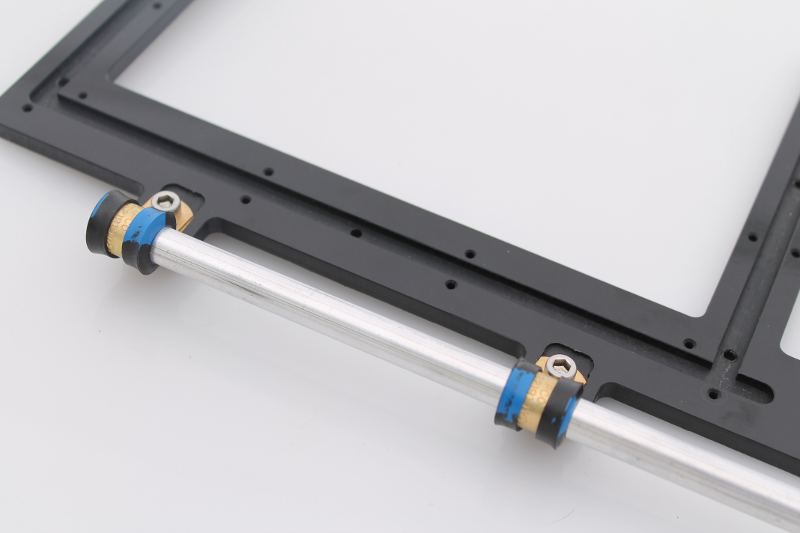
1) Photogate rod
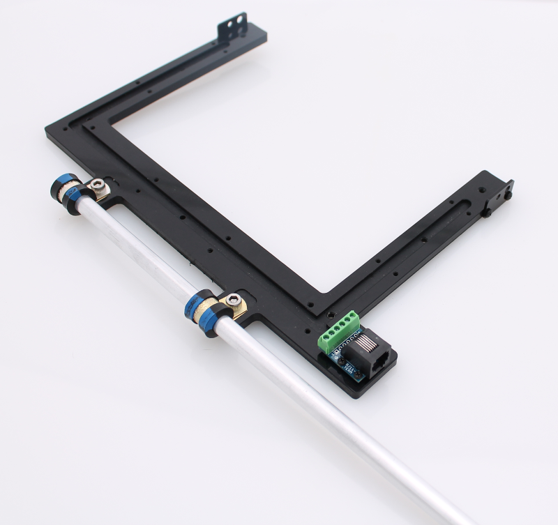
Use the 2 x loop clamps and 2 x 10-32 scews to attach the rod as shown in the images. Requires a hex wrench. (Parts # 1, 2 and 3 in List of hardware).
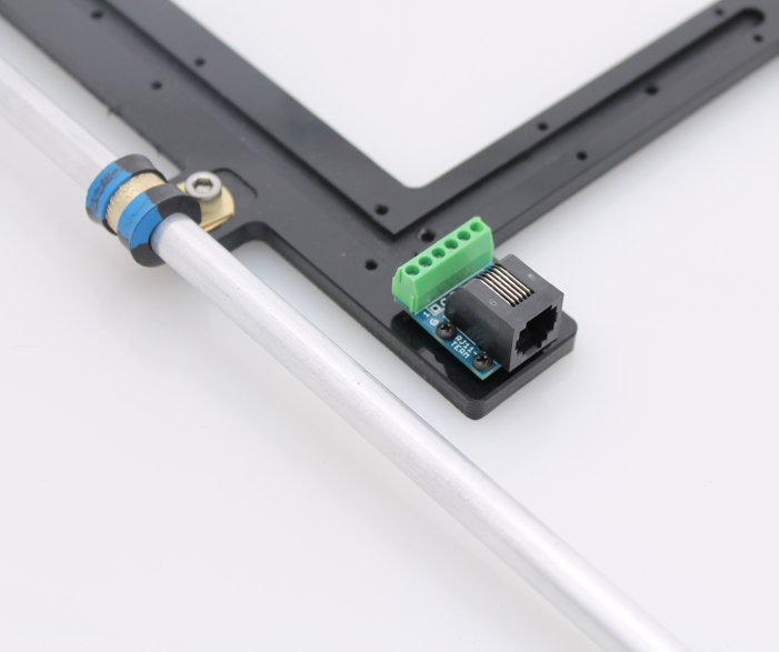
2) Gravitech RJ11 breakout board
Use the four 2-56 screws to mount the RJ11 breakout board to the photogate body. (Parts # 9, 10).
3) Laser cut sensor/led mounts
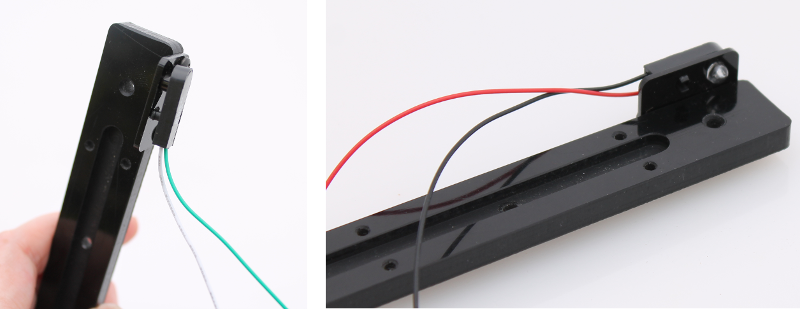
Use the 5/16” long 4-40 screws to attach the sensor/led mounts to the sides of the photogate. Orient the parts with the larger hole towards the top. (Parts # 4, 5).
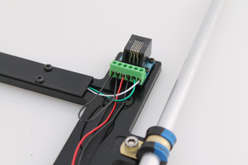
6) Wiring to the RJ11 breakout board
Cut and strip the four wires.
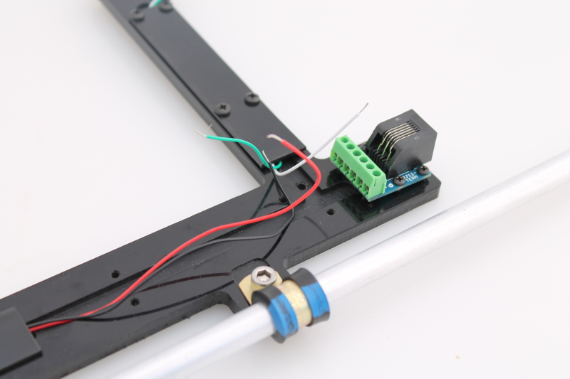
Using a small Philips blade screwdriver. insert and secure wires into the RJ11 breakout board as shown in the image below.
- Phototransistor wires first (white, green) followed by emitter LED wires (black, red).
Using some of the left-over black wire from the LED component, form a small u-shaped loop and place the ends into the last two terminal blocks. This is for the auto-detect function.