Step 2: Connecting motor to the speed control PCB
Mounting the PCB into the enclosure
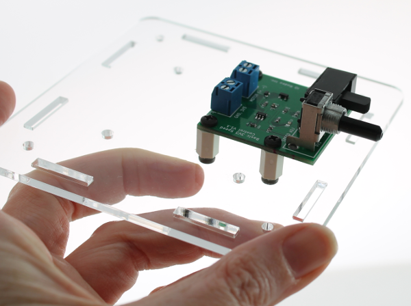
Parts: acrylic base plate, 8 x enclosure screws, 4 x PCB standoffs, speed control PCB
Mount the PCB onto the base plate as shown in the image below using the PCB standoffs and eight of the enclosure screws.
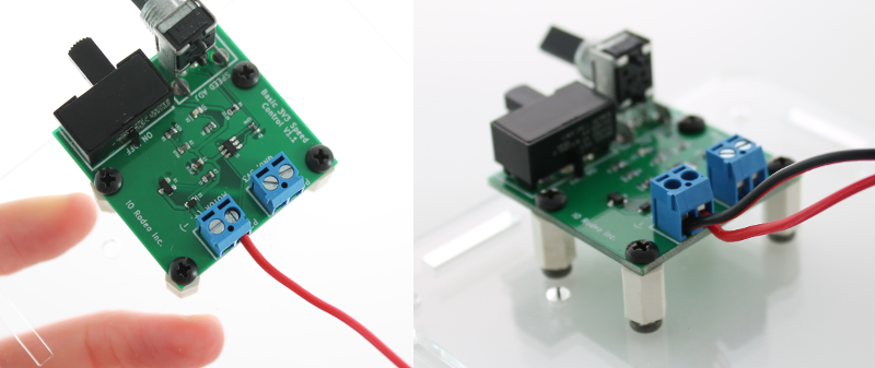
Connecting the motor to the PCB
Next you will connect the motor to the blue terminal block on the PCB labelled “Motor” (position P2). Insert the red wire into the part labelled as ‘+ve’ on the PCB. Using the flat-end of the scewdriver blade, screw down to secure the wire. Repeat with the black wire to the ‘-ve’ end.