Step 4: Assembly of the enclosure
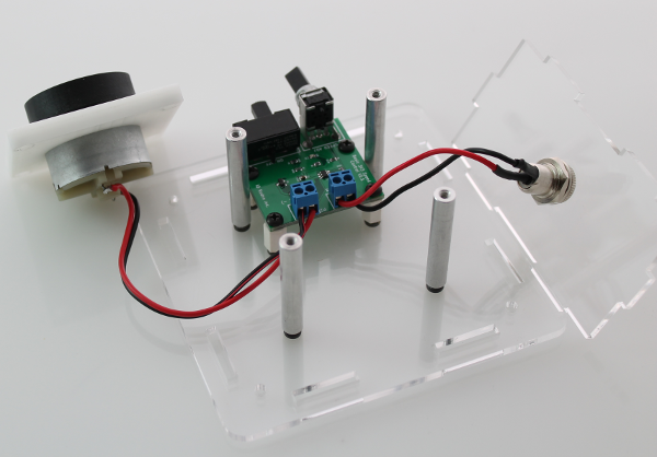
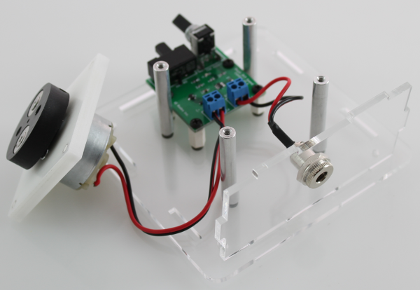
Mounting the motor
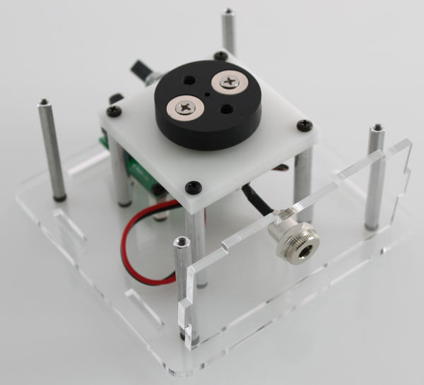
Parts: 4 x motor standoffs, 4 x enclosure screws, 4 x motor mount screws, motor/motor mount assembly
Place the four motor standoffs into the enclosure using four of the enclosure screws. Mount the motor onto the standoffs as shown in the image below using the four (longer) motor mount screws.
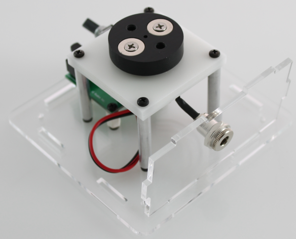
Assembly of arylic enclosure
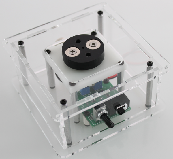
Parts: 5 x lasercut acrylic enclosure parts, 4 x enclosure standoffs, 8 x enclosure screws
Place the last four enclosure standoffs into the corner of the enclosure base using four of the enclosure screws. Place the remaining enclosure sides and top onto the enclosure. Use four of the enclosure screws into each of the corner standoffs to hold everything in place.
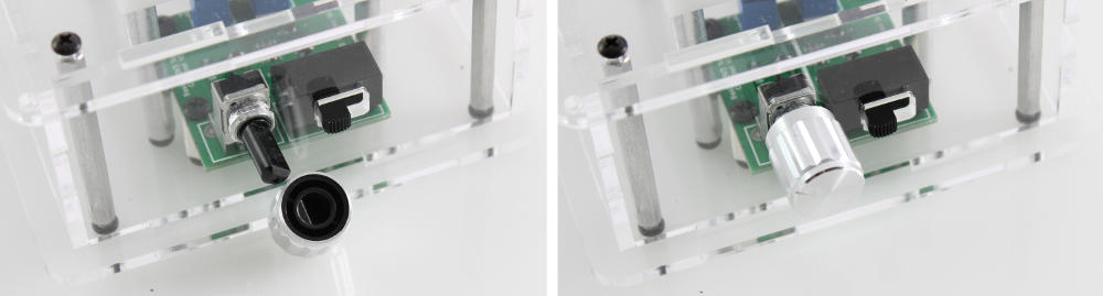
Add the knob for variable speed control
Parts: Knob for potentiometer
Press fit the knob onto the potentiometer as shown in the images below. Note: the knob has an internal notch which lines up with the flat side of the potentiometer.