Photogate software
Software is currently available for Windows and Linux.
- Windows - Download the Windows executable from https://bitbucket.org/iorodeo/photogate_software/downloads/photogate_v0.1.exe
- Linux - Source is available from https://bitbucket.org/iorodeo/photogate_software/get/default.tar.gz
Software Overview
As a moving object passes through the photogate, the object briefly interupts the IR LED beam, preventing light from reaching the phototransistor. Once the object has completely passed through the photogate, the IR LED beam is no longer interupted and light reaches the phototransistor.
The photogate software reports the time in seconds when the photogate IR LED beam is interupted i.e. the object entry and exit times.
- Entry time = time when the photogate is blocked (interupted) by object
- Exit time = time when the photogate is unblocked
These photogate timing values are used to return two very useful measurements:
- Time in gate - Time for the moving object to completely pass through each photogate, i.e. difference between entry and exit times.
- Time between gates - Time for the moving object to pass between gate 1 and 2, i.e. difference between Photogate 1 and 2 entry times.
An example is shown below:
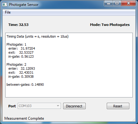
These values can be used to calculate the velocity and acceleration of a moving object. For example, experiments to determine acceleration due to gravity, (see Freefall - calculating g) or acceleration of an object on an incline (see Inclined plane - rolling ball).
Additional Software Features
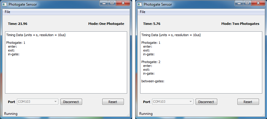
- Software can be used in both “One Photogate” or “Two Photogate” mode.
- Photogate auto-detect function automatically selects the correct Operating Mode.
- Data can be saved in 3 different formats. Matlab (.mat), Comma separated values (.csv) and plain ascii text (.txt).
- When used in Two Photogate Mode, Photogate 2 remains inactive until Photogate 1 is activated.
- Timing reset function. Click on the Reset button anytime to clear data and re-start the photogates. Note that any data will not be saved.
Using the photogate software
- Before starting, make sure the Arduino is programmed with the photogate firmware as described in Programming Arduino with photogate firmware
- Download and launch the photogate software. The screenshots shown here were taken using the photogate software for Windows.
- Connect the Arduino to the PC with the USB cable. In the photogate software screen, select the device port from the drop-down menu. The photogate software automatically detects all available serial ports so you should be able to select from the drop-down list.
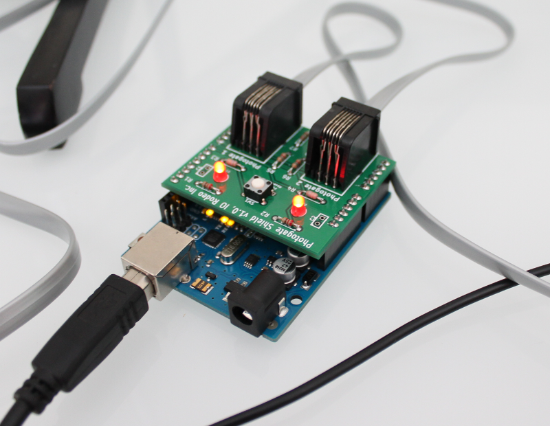
Connect photogates
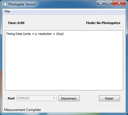
Connect the photogates to the Arduino shield. The software auto-detect feature automatically detects the number of photogates connected and selects the operating mode. As shown in the screenshots below, mode should change from “No photogates” to “One photogate” or “Two photogates” Additionally, on the Arduino shield a red led will indicate once the photogates are connected.
Start measuring
That’s it ! You are ready to start using the photogates. On the next pages are some examples of using the photogates.